Reverse Engineering at CADEC Limited
Step 1: Capturing the Object
The first step is to determine the most suitable approach for capturing the component’s details. This depends on factors such as the complexity of the geometry, accuracy requirements, and intended use of the final output. Common approaches include:
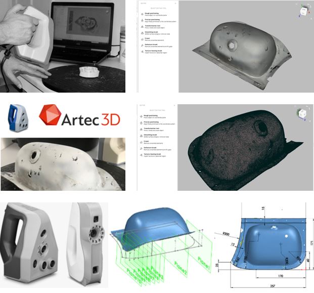
- 3D Scanning:
High-resolution scanners are used to capture detailed surface geometries. This method is ideal for freeform shapes or components with intricate details that are difficult to measure manually.Output: A point cloud or mesh dataset that reflects the physical object’s shape. - Manual Measurements:
For simpler components or when scanning isn’t feasible, precise tools like calipers, micrometers, or coordinate measuring machines (CMMs) are used to record dimensions.Output: A set of dimensional measurements used as the basis for CAD modeling. - Component Disassembly and Study:
In cases involving complex assemblies or internal features, the component may be carefully disassembled and analyzed. This approach is particularly useful for understanding internal geometry, materials, and assembly techniques.
Step 2: Data Processing
Once data is gathered, it must be processed and refined to create a usable foundation for modeling. This stage includes:
- Cleaning and Refining Data:
- For scanned data: Noise or artifacts introduced during scanning are removed to ensure the dataset accurately reflects the original object.
- For manual measurements: Data is organized into sketches or tables that can be used in CAD software.
- Aligning and Structuring:
- Scanned data is aligned within a coordinate system to match engineering standards.
- Measurements are interpreted and structured into an initial design framework.
- Polygon Optimization (For Scans):
Reducing the density of the mesh to simplify data while retaining critical geometric features. This ensures efficient handling in CAD software. - Cross-Verification:
The processed data is compared to the original component using inspection tools to confirm accuracy and fidelity.
Step 3: CAD Modeling
With the processed data, the engineering expertise required to develop a usable CAD model comes into play. This step involves:
- Reconstructing the Geometry:
- For scanned data: The point cloud or mesh is used as a reference to build a parametric 3D model. Engineers interpret the raw geometry, identifying design intent and resolving irregularities.
- For manual measurements: Sketches and dimensions are transformed into 3D shapes, often starting with key profiles and extruding, revolving, or sweeping them to build the overall form.
- Adding Design Details:
Essential features are added, including:- Holes, threads, slots, and other functional details.
- Fillets, chamfers, or other finishing features for manufacturability.
- Tolerances and fits for assembly compatibility.
- Output as a Parametric Model:
The final CAD model is parametric, meaning it can be edited or adjusted in the future for design changes, optimization, or further analysis. - Documentation (if required):
- 2D engineering drawings can be generated from the CAD model, showing all necessary dimensions, tolerances, and notes for manufacturing.
- Additional documentation can include exploded views, cross-sections, or material specifications.
Applications
Our reverse engineering services can be applied in a variety of contexts, including:
- Reproducing Discontinued Parts: When original documentation or suppliers are unavailable, reverse engineering allows accurate reproduction.
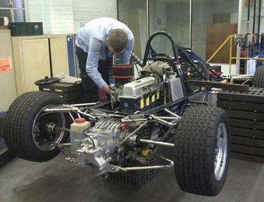
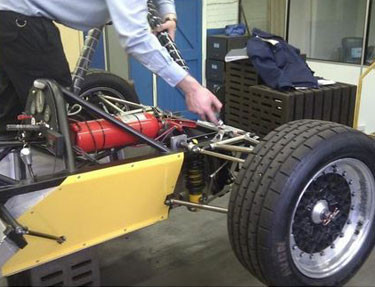
- Restoration and Heritage Projects: Classic cars, machinery, or other heritage items can be restored with accurate replacement components.
- Design Optimization: Analyze existing designs for opportunities to improve performance, reduce weight, or simplify manufacturing.
- Inspection and Quality Control: Validate manufactured parts by comparing them against original designs.
Case Studies
Classic Car Restoration
We supported a restoration project by reverse-engineering a series of vintage car parts, including intricate trim pieces and mechanical components. Using a combination of 3D scanning and manual measurements, we ensured historical accuracy and seamless integration with the original vehicle.
Industrial Heater Component
An industrial client required a replacement for a critical heater part no longer in production. We scanned the worn component, processed the data, and delivered a CAD model optimized for modern manufacturing methods, ensuring compatibility with their system.
Aerospace Component Analysis
In an aerospace project, we reverse-engineered a damaged hydraulic actuator, using disassembly and measurement techniques to recreate internal and external geometries. The final CAD model allowed for an improved and more reliable replacement part to be manufactured.


